Update: Dec 2015. While doing this task it would not hurt to also perform some preventative tasks such as the turbo oil return line, turbo oil feed line shielding (for the ones that did not come with factory installed shielding), and oil filter housing gasket/seal replacement. All of these I have had to do, but if you're already taking the down pipe out might as well save some time and do these cheap preventative tasks.
The oil feed line is faulty for all N14 engines (Mini might have fixed the problem in new models, but since they never confirmed that was a problem who really knows?), which includes pretty much all Mini turbocharged engines. The failure of these lines is usually around 40-50k miles. The design flaw is that Mini used a rubber o-rings in the banjo bolts that connect the line to the turbo. The problem with that is the turbo gets really hot. The constant hot and cold cycle eventually destroys those o-rings and a leaky oil feed line is the result. Mini knows about this problem and even though this part is flawed no recall has been issued. I'm guessing the main reason is that the labor for replacing this line runs about $1200, while the OEM part is about about $70-80.
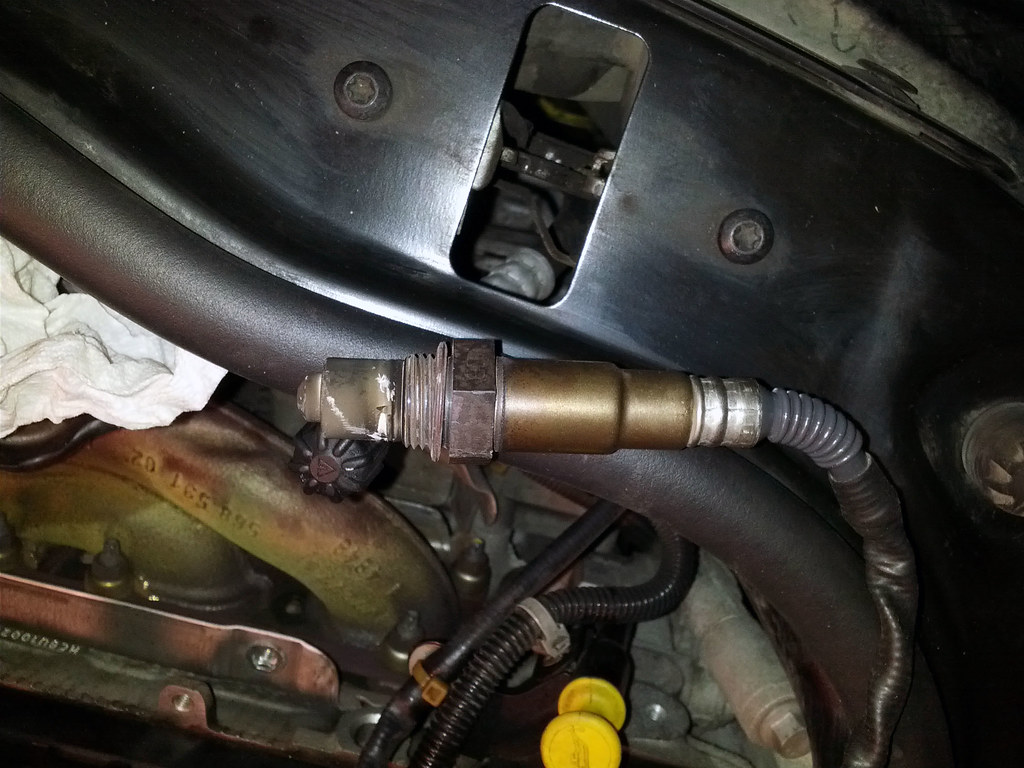
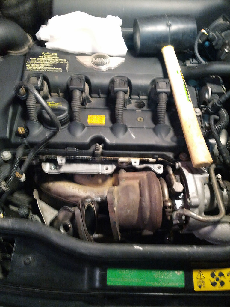
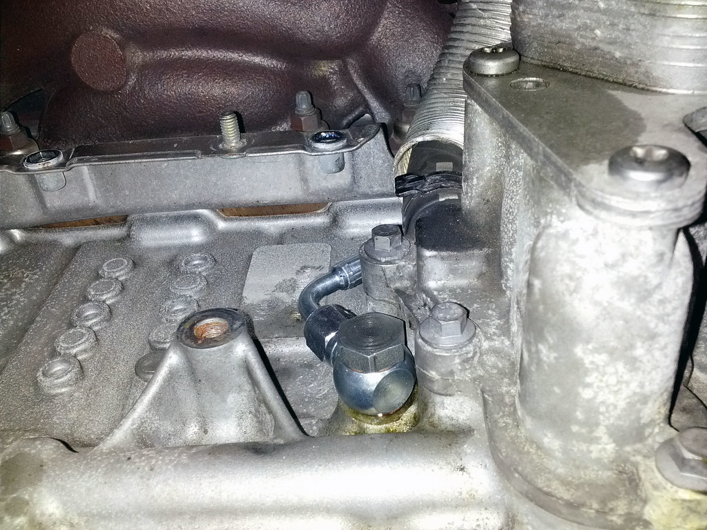
This is a pretty major problem because oil is essential in keeping the turbo cooled. If your turbo cooks you're looking at several thousand down the drain. Furthermore the Mini N14 engine already consumes a lot of oil, add in a leak like this you're doing to have a lot more problems if you don't keep your oil levels in check. The symptoms of the problem is easy to spot. The top banjo bolt that connects to the turbo can be easily seen. If there is any discoloration or wet oil spots around that connection, then the problem has already started. I initially noticed a small ring of oil around that connection. A month went by while I closely monitored the leak and oil levels. After talking with Mini of San Diego and getting a $1200+ quote, I decided to this fix myself. Below is a picture of what my turbo oil feed line looked like just before I replaced the oil feed line, this is at 53k miles. Notice the dark oil stains around the banjo bolt.
Parts
- Oil Feed Line (1 end with a 90 degree bend)
- 2 Banjo Bolts
- 4 Crush Washers
- Turbo to Downpipe gasket
- Exhaust V-clamp
- 3 turbo to downpipe bolts (optional)
Tools
- PB Plaster
- Anti-seize
- Metric Ratcheting wrenchs
- Metric Sockets - Regular and Deep wall
- O2 Sensor Socket or a 22mm wrench
- Various length screw drivers
- Low profile ratchet (recommended)
- High tooth ratchet (recommended)
- Rubber mallet
- Ducktape
Torque Specs
- V-Clamp 25 Nm/18.4 ft-lb
- O2 Sensors 50 Nm/37 ft-lb
- Oil Feed Line Banjo Bolts 30 Nm/22 ft-lb
- Support Bracket to Engine Block 19 Nm/14ft-lb
- Turbo Charger to Exhaust Manifold 20 Nm/14.7 ft-lb
Labor ~ 2days
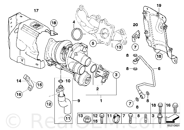 |
| Exhaust Manifold Diagram |
The Mini Stealership wanted $80+ for just the line show as #6 above, probably the same faulty line that was originally in my car. Since turbo oil feed lines are nothing special or unique to Mini, I decide to go aftermarket. You can pretty much order any turbo oil line in size 4A with length of about 16-18in. One end of the line needs a 90 degree bend and other can either be straight or a slight 10-15 degree bend. The banjo bolts are standard 12mm.
Pretty much any auto store that stocks turbos will have turbo oil lines. The Mini OEM line is rigid and there are bends already in the line, aftermarket lines are stainless steel braided and they are completely flexible which makes install much easier. I did some research and found TechnaFit which stocks a Turbo Line Kit (Kit MCTL-0911) for Mini Coopers.
Although the title says 09-11, this kit does fit my 07 and I'm fairly certain all other N14 engines as well. And although the pictures shows straight connectors, they are actually bent at 90 degrees for the bottom connection and a slight 10-15 degrees for the top connection.
 |
| Downpipe Diagram |
In addition to the turbo oil line kit, I also purchased a turbo-downpipe gasket (#2 above), 3 turbo-downpipe bolts (which I ended up not needing) and finally an exhaust v-clamp (#6 above). This brought the total to <$70.
 |
| Lower O2 Sensor |
This repair, requires access to the top and bottom of the front engine compartment so jack stands are necessary. Once the car is on stands I would start off by soaking the turbo-down pipe connection area, v-clamp area and the upper and lower oxygen sensors with pb blaster. The upper oxygen sensor is easily spotted to the left of the turbo. The lower oxygen sensor is attached to the bottom of the downpipe. This will give it some time to penetrate while you work on other things.
 |
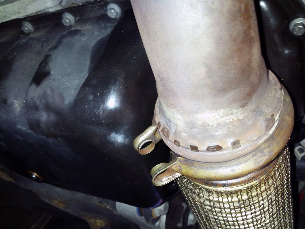
| V-Clamp |
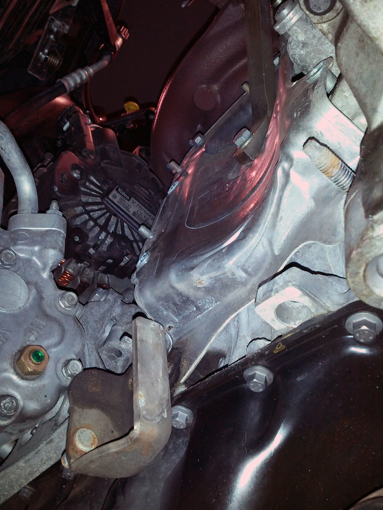
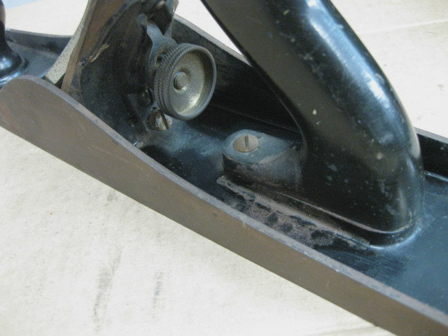
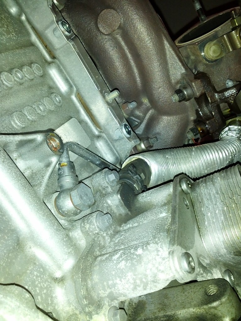
Remove the top heat shield (#17 - Exhaust Manifold Diagram). This is held on but six 10mm screws. The top three are easy, the bottom 3 are extremely difficult to get to. The clearance is limited. I had to improvise and create extended ratchets using screwdrivers and both my 1/4" and 3/8" ratchets to reach those screw. To the left of the downpipe is the black flap that says Castrol on it. I loosened the bolt on that piece and rotated it out of the way. This is is the part that took a lot patience and time, below is what the turbo looks like with the heat shield removed and the two makeshift tools I used to remove the lower screws.


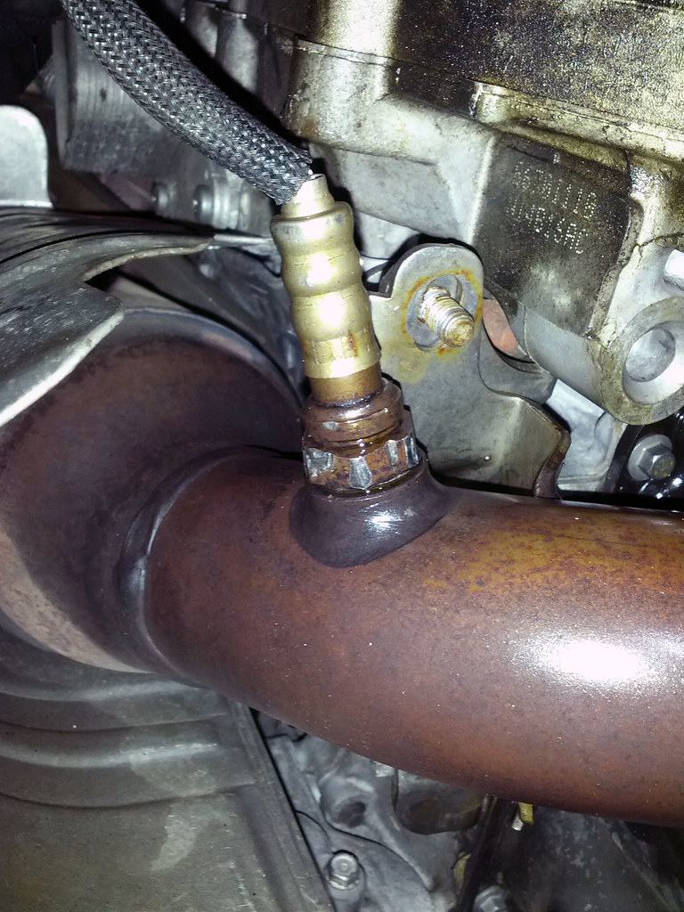
Once all the screws are out, you must remove the oxygen sensor before removing the heat shield. Use an oxygen sensor socket to remove the top oxygen sensor. I didn't have too much trouble with this one but additional pb blaster and a breaker bar may be necessary. Be real careful as not to damage the sensor. move the sensor off to the side. Below is the oxygen sensor.
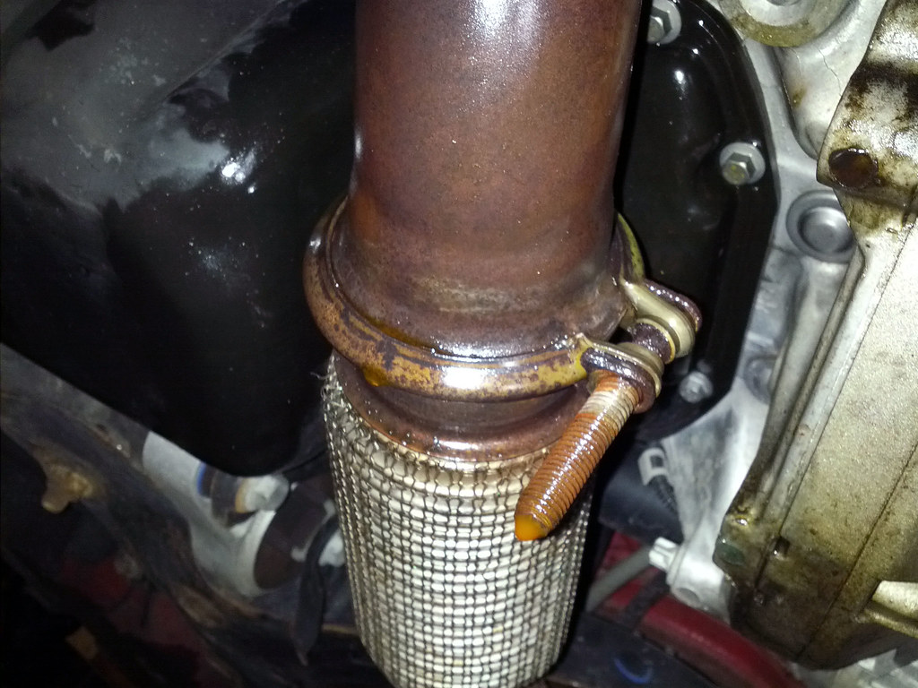
Next I removed the lower oxygen sensor and v-clamp. For me both these two items took overnight soaking of pb plaster before I could get them removed. I ended up almost breaking my O2 socket. I eventually used an open ended wrench to remove this sensor. I duct taped the sensor off to the side so it is out of the way.
My V-clamp was so rusted that the bolt fell apart. I used a hammer to get the bolt out. Even with bolt off the ring was still welded on. It took more pb plaster, hammering and prying to get the clamp off. This was probably one of the more frustrating parts for me. I decided to replace the V-clamp with a new one.
I then moved to the lower heat shield (#5 downpipe diagram). This one uses the same 10mm screws as the other heat shield. There are four to remove, two on each side. This heat shield cannot be extracted until the downpipe is loosened and removed first, so just let it sit there for now.
The bottom of the downpipe has two brackets (#4-downpipe diagram) that attach the downpipe to the engine. There are four nuts that connect the two brackets to the engine and downpipe to the brackets. I removed the nuts that connected the downpipe to the bracket and I only loosened the nuts connecting the bracket to the engine, leaving the two brackets loosely hanging.
With the bottom of the downpipe detached, I moved to the top connection. I used a deep wall socket to remove the 3 nuts that connect the turbo to the downpipe. I was told that sometimes these nuts and bolts need to be replace. For me all three nuts were removed without any problems. I read that sometimes the studs will come off and the nuts are actually welded onto the stud!
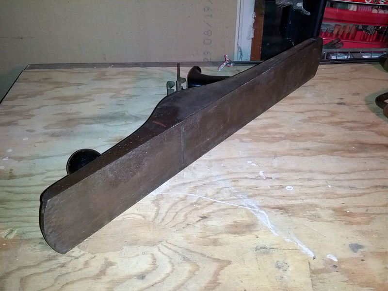
With the downpipe completely detached from the top and bottom, I used a piece of scrap lumber and a rubber mallet to get the downpipe to detach from the turbo. At one pointed I also used a pry bar wrapped in a towel so I wouldn't scratch things up.
Now that the downpipe is detached from turbo, wiggle the lower heatshield and the downpipe. This takes some fiddling around but eventually I was able to work the downpipe down and out the bottom. The lower heatshield was removed afterwards. I ended up removing the brackets too, I'm not sure if this step was necessary but it made re-install much easier.
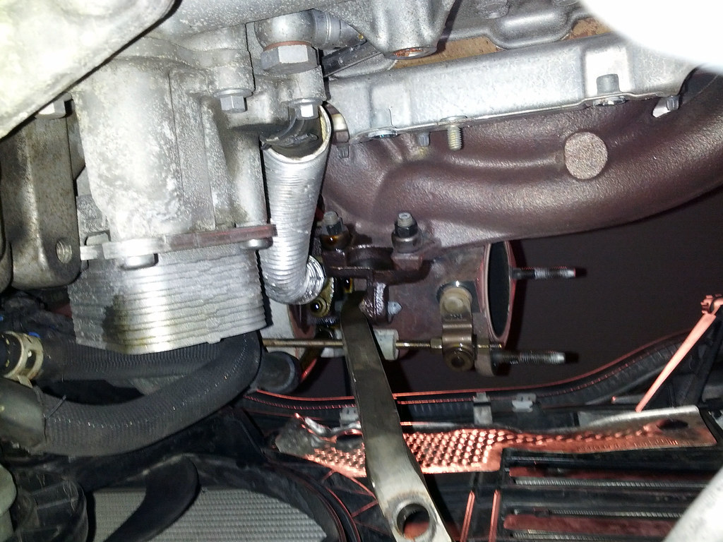
Now that the lower heat shield and downpipe is removed there is a lot more space and you should be looking up into something that looks like this. I saw some oil and decided to take this opportunity to clean all that up.
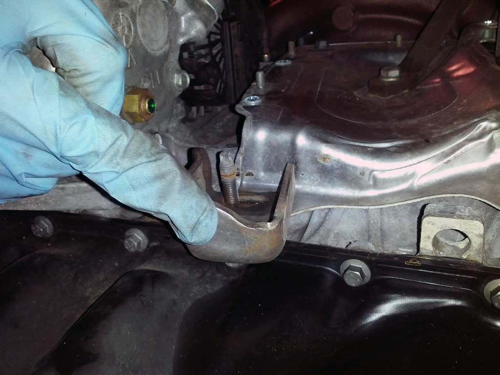
The final heat shield needs to be removed. However this shield is blocked by a support arm bolted to the middle of the heat shield to the engine block. The bolt is a 13mm. That bolt needs to be removed and the pivot bolt needs to be loosened. Then the support arm should swing out of the way.
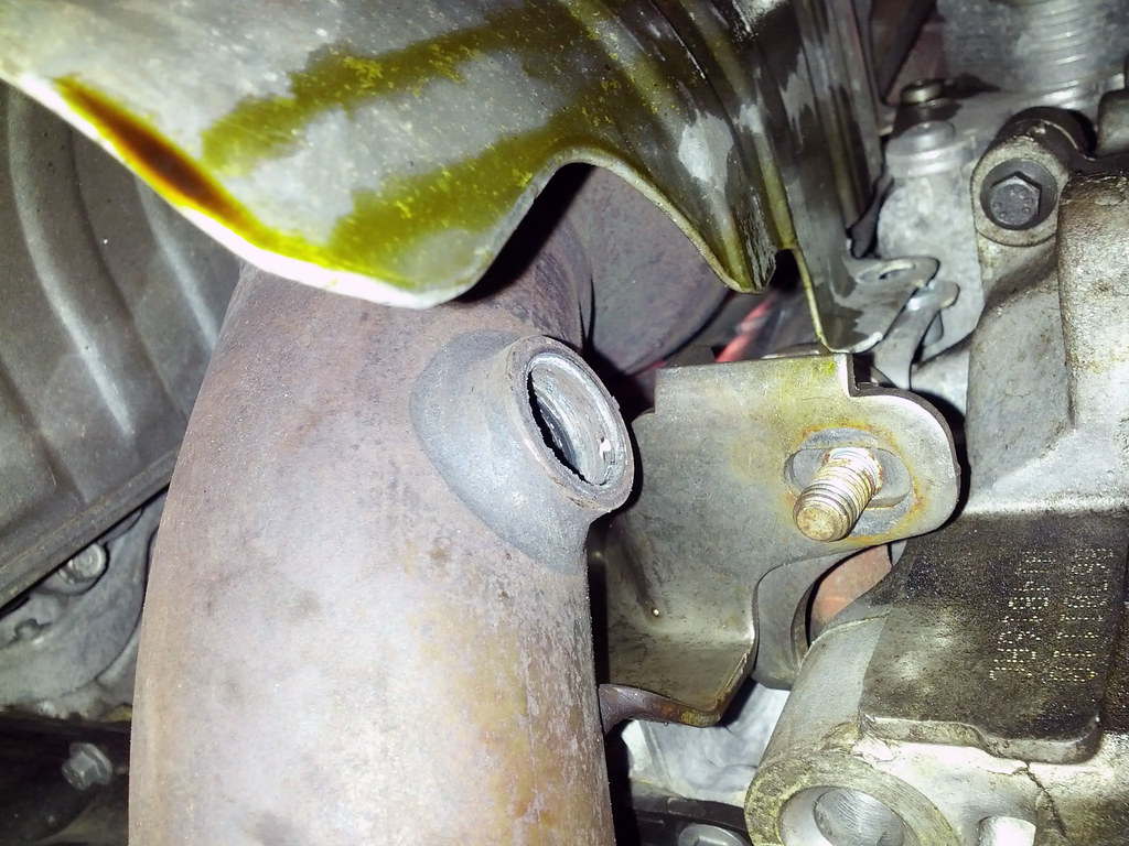
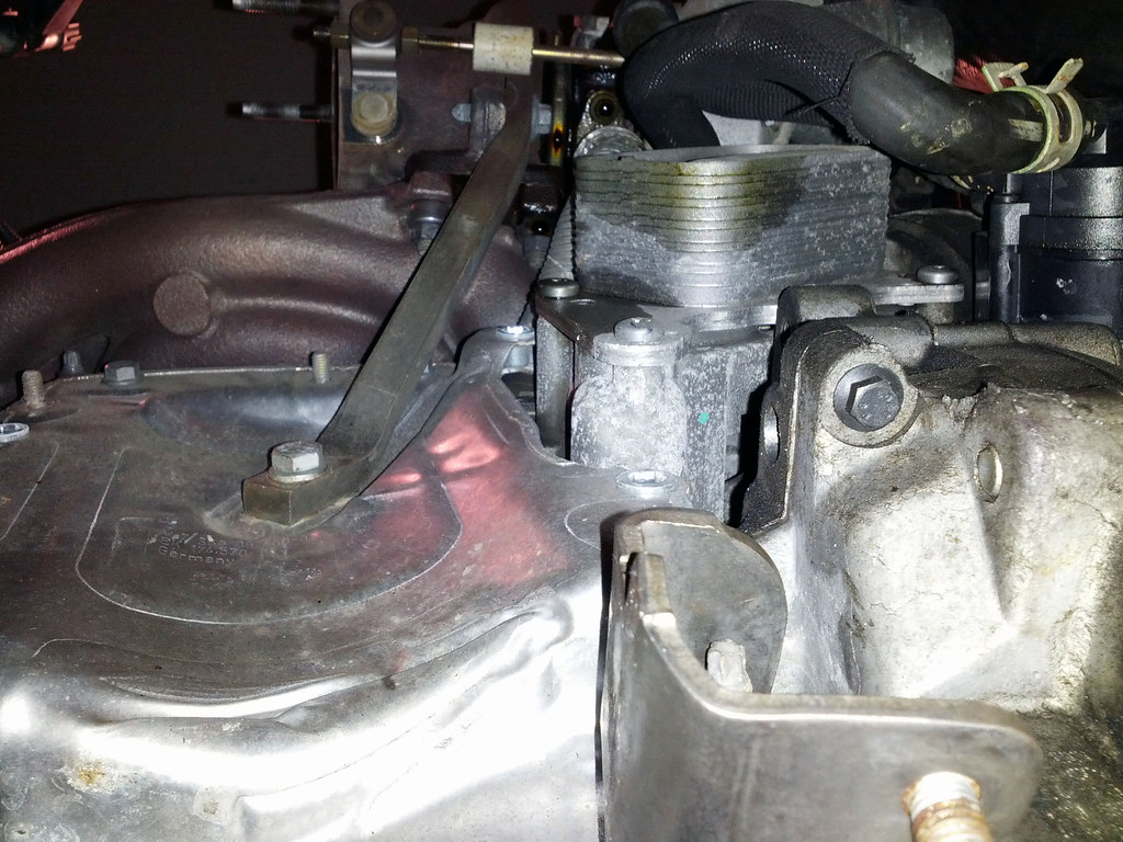
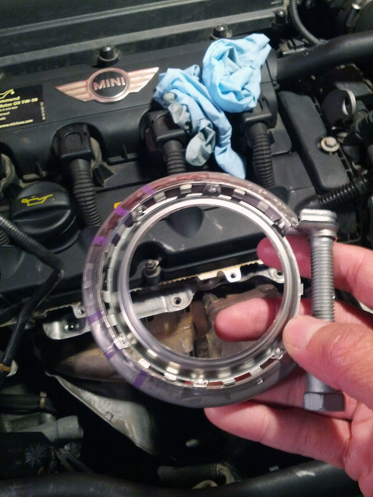
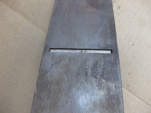
With the final heat shield removed it should look something like this below. You should now be able to see the bottom connection point of the turbo oil feed line. All the previous work was just to get to this connection point.
 |
| Old oil line |
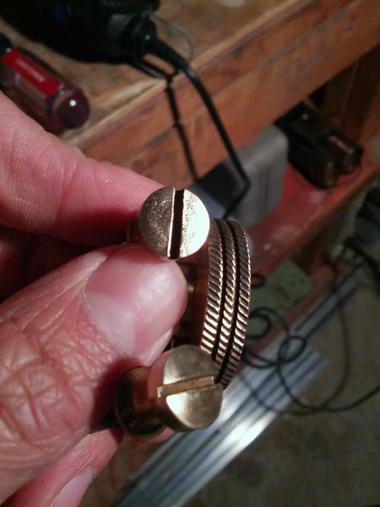
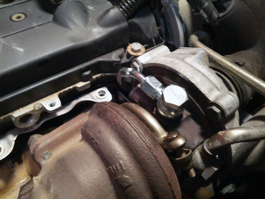
At this point remove the oil feed line. Since the OEM line is rigid it takes some fiddling to get it out. The new line, if you went the stainless steel braided, is much easier to install. Make sure you use two crush washers for each banjo bolt. Install the new line with the 90 degree bend at the bottom. I inserted the line from the top to bottom. My new line looks like this.
 |
| New Stainless Steel Braid Line |
 |
| New Stainless Steel Braid Line |
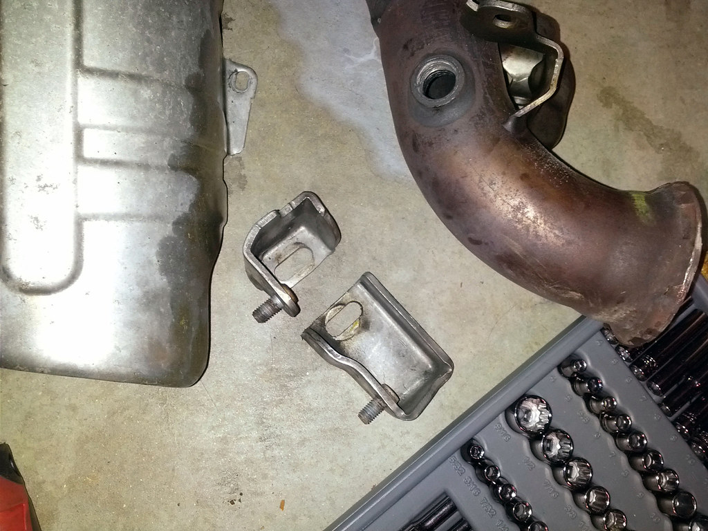
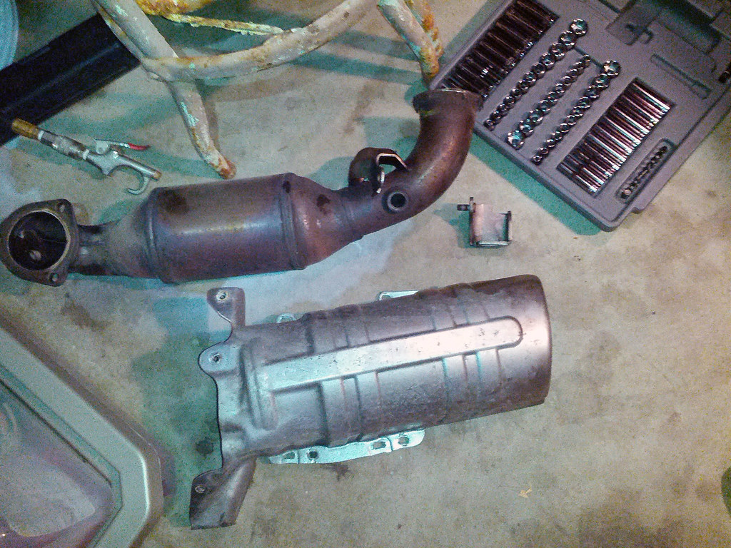
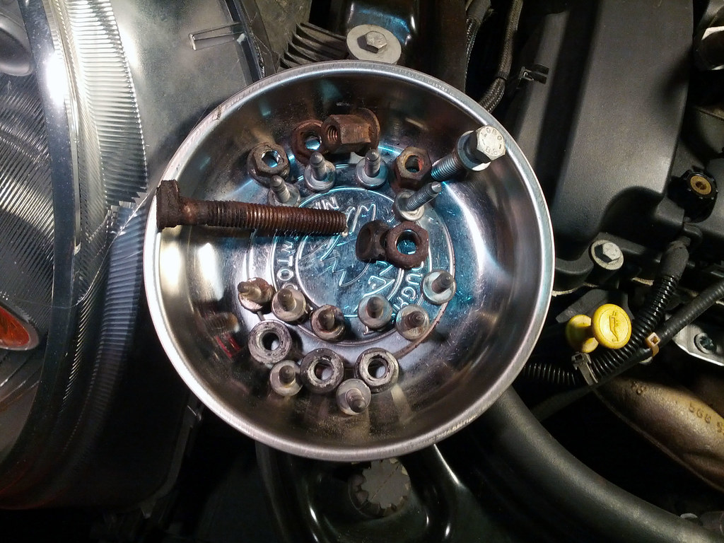
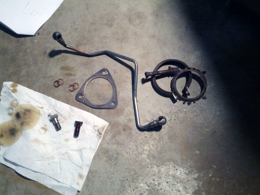
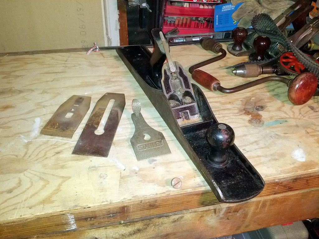
To get to this point, here is all the hardware I had to remove and the faulty oil line.
After the new oil line is installed, I just worked backwards and re-installed all the parts. I put anti-seize in the threads of the O2 sensor, just in case I need to get those things off again. I replaced the gasket between exhaust manifold and the downpipe as well as the V-clamp between the downpipe and exhaust.
This process took two days. It probably could have only taken one if I didn't have to let the pb blaster soak in for the V-Clamp and O2 Sensor removal. I would definitely recommend replacing both the V-clamp and gasket at the minimum.